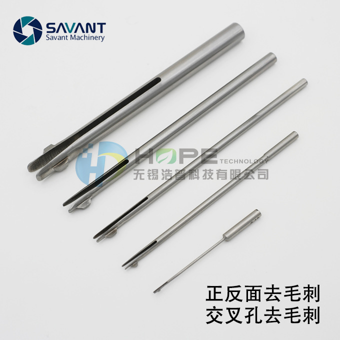
SAVANTEC once through and double chamfering tool (inner and outer hole deburring and chamfering tool) is a deburring and chamfering tool designed for batch processing environment. The design of integrated rotating body cutter makes it possible to form multi-faceted chamfering and deburring at one time, While solving the problem that the inner end of the hole cannot be chamfered, it is more convenient to discharge the debris generated by processing, so as to avoid delaying the construction period due to tool blockage.The convenient maintenance mode enables the blade to grind without unloading.
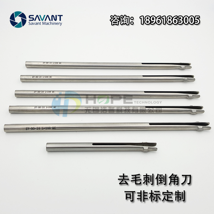
SV-BO deburring and chamfering tool is a tool for deburring the front and back sides of orifices on plane or curved surface in a single process Its simple design principle makes it possible to complete the burr removal of the front and back orifices without turning the workpiece or stopping the spindle.
It is mainly used in CNC machine tools in mass parts production. Of course, it can also be used for deburring of manual bench drill and rocker drill. The range of SV-BO standard tool is D0.8mm to 10mm. For hole deburring greater than 10mm, we recommend using SV-BW deburring tool. You can also customize large-size SV-BO series tools without standard.
Tool characteristics
The tool relies on the plastic deformation of the material to complete the through hole
The transition between the upper and lower cutting edges is smooth, which ensures that the hole wall will not be scratched by the tool through the hole (there will be slight marks below roughness Ra0.8). The heat treatment hardness of M42 high speed steel is 63hrc, which effectively ensures the wear resistance and overall toughness of the tool edge.
Tool description
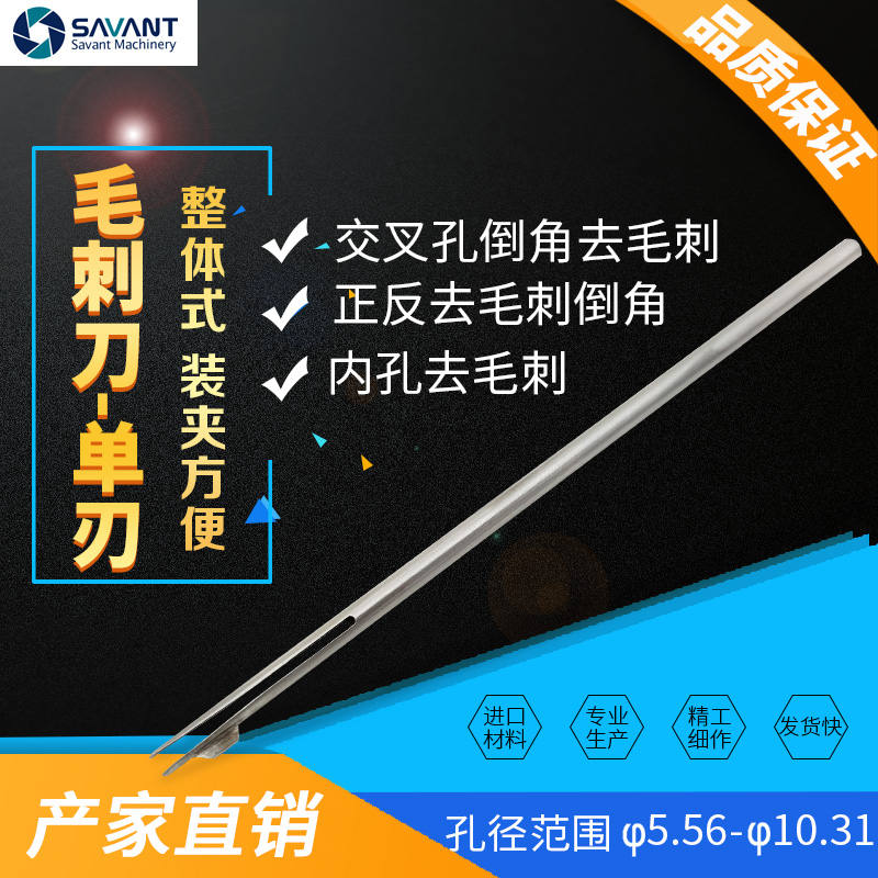
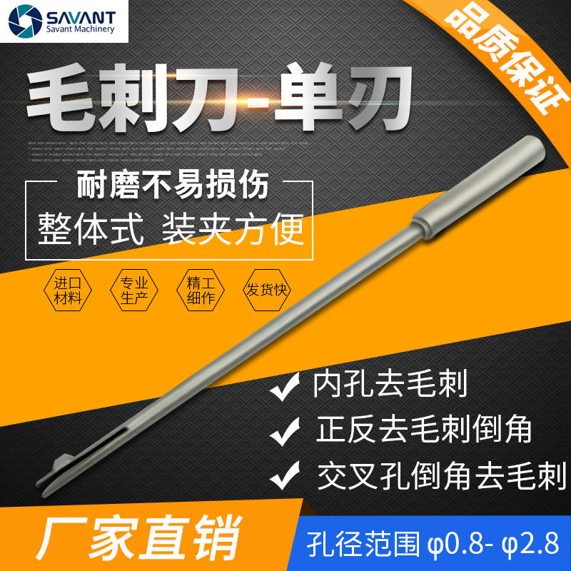
SV-BO front and back deburring chamfering cutters are divided into three categories: unequal handle single edge - mainly for small holes ranging from 0.8mm to 2.8mm, equal handle single edge - mainly for holes ranging from 2.8mm to 5.56mm, and equal handle double edge - mainly for holes ranging from 5.56mm to 10.31mm.
Deburring chamfering cutter - unequal shank single edge
Recommended feed f = 0.05-0.2mm/rpm Tool usage steps
1. Quickly move the tool above the workpiece orifice by referring to the distance a between the end face of the cutter bar and the orifice
2. Process forward in the way of work progress to the position where the distance between the end of the cutter rod and the orifice is B (ensure that the blade has been fully integrated into the cutter body)
3. The distance from the quick through hole to the end of the cutter rod to the back of the hole is equal to C, so that the blade can be fully extended
4. Reverse work to remove the burr on the back until it is fed to the position where the end surface of the cutter arbor is d away from the back of the hole, and then the cutter can quickly move out of the hole
Note: when the orifice is curved, please consider the unevenness value x when programming( (i.e. take x as part of the workpiece material)
6 Machinable slope
The deburring tool for the front and back holes of SV-BO has requirements for the aperture ratio, and the maximum aperture ratio (d: D) is about 0.5.The angle corresponding to the inclined plane where the base hole is located is within 15 °.
If the aperture ratio (d: D) of the base hole and the main hole is greater than 0.5, it means that the inclination is greater than 15 °. We can only modify the main deflection angle and rear angle of the blade (we need to test whether it can meet the customer's requirements)
When machining through perforation as shown in the figure, the spindle speed needs to be reduced and the feed remains unchanged.
7 Problem solving in deburring and chamfering
Fault phenomenon
Cause
Solution
The Chamfer dimensions on the front and back sides of the hole opening are inconsistent
U the feed rate in the forward and backward directions is inconsistent U the thickness of front and rear burrs is inconsistent
ü the feed rate can be reduced on the side where the chamfer is too small ü the feed rate can be increased on the side where the chamfer is too large
The chamfer is not machined
The U blade is too blunt U burr too thick
ü replace with a new knife ü replace the drill bit
The chamfer size is too small and the burr is not removed
ü feed rate too large
U lower feed
Chamfer size too large
ü feed rate is too small ü tool size selection is too large
ü can increase the feed speed ü select smaller size tools
Uneven chamfer
U speed too high U the diameter ratio of small hole to large hole is too large
U reduce speed ü too large aperture ratio cannot be solved with SV-BO tool
Chatter marks appear on the chamfered surface
U the fixing strength of workpiece or blade is not enough U the tool is in an unstable state U speed too high
ü ensure that the workpiece and tool are fixed firmly ü increase blade feed U reduce speed
Secondary burr
U feed too slow U the cutting edge is too blunt
ü increase feed ü replace with a new cutter
SV-BO deburring and chamfering cutter for front and back sides is also suitable for manual machining, but it is recommended to clamp the cutter on the pistol drill and move the workpiece for machining:
The simple design of deburring and chamfering cutter on the front and back sides is suitable for improving deburring efficiency and stabilizing production. The tool does not require a complex or time-consuming preset process. The diameter of the drill hole determines the size of the tool bar required. The size of the chamfer can be adjusted by the adjusting screw at the tail and the feed rate
It is a company integrating tool R & D, production and sales, specializing in deburring tools and flexible floating tools
No. 26-6, Huibei Road, Jinshan North Industrial Park, Liangxi District, Wuxi City, Jiangsu Province
 简体中文
简体中文