简体中文
简体中文 


1 Tool Description

POS. | explain |
1 | cutter arbor |
2 | BW blade |
3 | Pin |
4 | Spring |
5 | regulating screw |
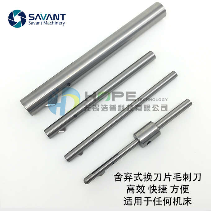
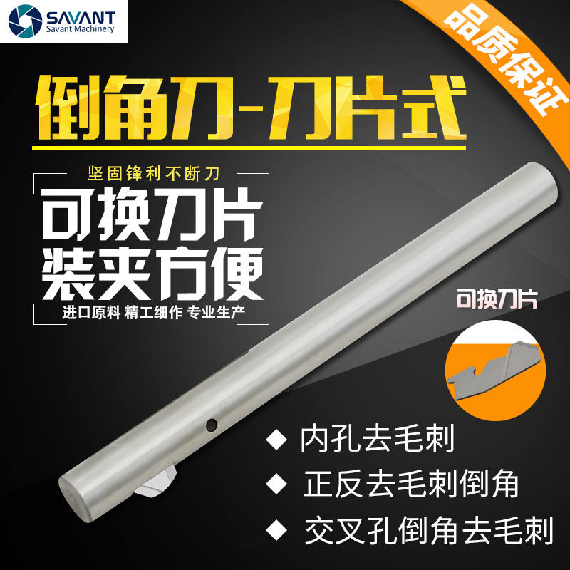
SV-BW series deburring and chamfering tools for front and back orifices are a simple and flexible chamfering and deburring solution to meet the requirements of modern production. The SV-BW deburring and chamfering tool makes the forward and backward deburring process easier, and the blade can be easily replaced manually. The whole sv-bw system is only composed of five simple components to improve the stability of the product. Deburring or chamfering the through hole can be completed in only one machining process without changing the direction of the spindle. The front rotation of the spindle fits the front machining of the tool to achieve the front chamfering. Once the chamfer reaches the preset size, the blade will get into the cutter arbor and then move through the workpiece quickly.Once it passes through the rear side of the hole, its internal working mechanism will make the blade return to the initial position, and the reverse linear feed will process a suitable backward chamfer. The simple design of SEVANTE deburring and chamfering cutter is suitable for improving deburring efficiency and stabilizing production. The tool has no complex or time-consuming preset process. The diameter of the drill hole determines the size of the cutter arbor required. The size of the chamfer can be adjusted by the adjusting screw at the tail and the feed rate. The circular arc design on the side of the blade avoids the scratch on the hole wall when the blade passes through the hole, which will only slightly squeeze the inner hole and will not cause hole expansion. In order to ensure production efficiency, the tool can always rotate into the hole. |
Function In the natural state, under the action of spring pressure, the pin will push the blade out of the cutter arbor. When the forward and reverse cutting blades enter the hole, the burr at the hole will be removed and chamfered. When the tool passes through the hole, the blade will automatically enter the inside of the cutter arbor. Relying on the smooth arc surface design, the scratch on the hole wall when the blade passes through the hole is avoided. Reverse working produces a backward chamfer without stopping the spindle or changing the speed of the spindle. After finishing the machining of backward chamfer, the tool can return to the starting position by rapid feed. The blade will return to its natural state due to the force of the spring The forward and reverse deburring or chamfering operation can be successfully completed through this machining method. |
|


Tool characteristics Ø The rigidity of the tool is considered in the structural design of the blade and tool body, and the close cooperation improves the strength of the tool body and the stability of the system Ø The simple structure design makes the maintenance of cutting tools simple and rapid.
|
|
Ø The ingenious mechanical structure ensures the reliability of the tool Ø BW tool is easy to use without complex preset |
|
Ø The tool structure design is simple and reliable |
|
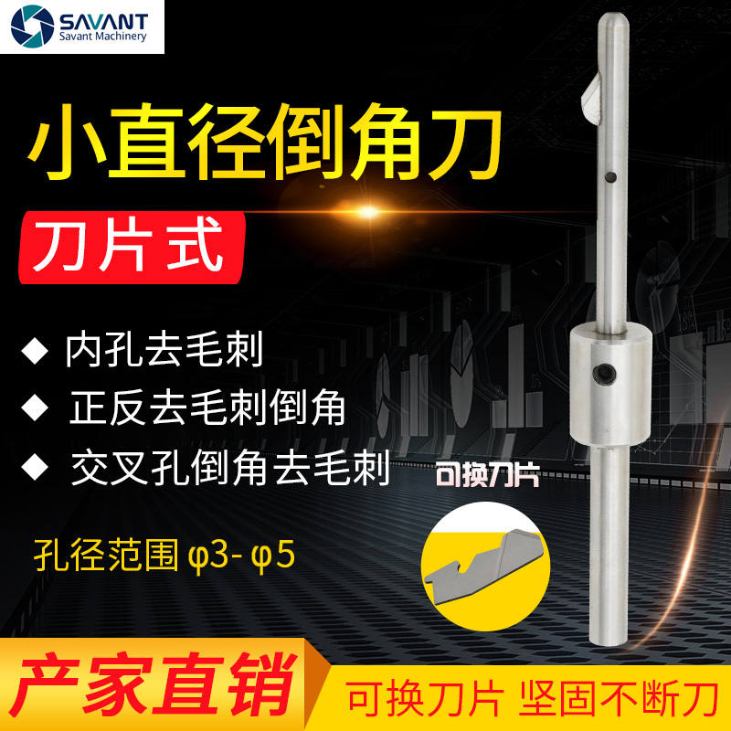
Ø The circular arc shape on the side of the blade is designed to avoid scratching the inner wall when the blade passes through the hole. |
|
Ø Using SV-BW tool holder can greatly expand the machining range of SV-BW tool. Ø As the R&D and manufacturer of SV-BW tools, we can also customize non-standard tools according to customer requirements。 |
|
Ø SV-BW tool is suitable for machining all kinds of materials from soft to hard (the maximum machining hardness can reach 50HRC). The tool can be adjusted by elastic adjustment during use. The longer blade edge prolongs the service life of the blade. | |
Ø The tool can be used for deburring threaded holes (the chamfer size needs to be greater than the pitch) |


Click to view the processing video:
2 Tool selection
Tool selection: The aperture size determines the order number of the tool and the order number of the blade. The model of the standard tool is shown in the figure. The diameter of the tool bar of the standard tool is 0.2mm smaller than the model value (the diameter of the tool bar below bw-6 including bw-6 is 0.1mm smaller than the model value) | |
Ordering example: | |
① Aperture: 10mm | ②Aperture::9.9mm Tool model::SV-BW-10 Blade model:SV-3# |
③Aperture:11.5mm Tool model:SV-BW-11.5 Blade model:SV-3-1/2# | ② Aperture:10.5mm Tool model:SV-BW-10.5 Blade model::SV-3-1/2#
|
Note: Please select the type according to the size difference of hole diameter tolerance. The above dimensions are the lower difference dimensions. | |
Small hole changeable blade chamfering cutter
Structure diagram

Model | L | L1 | L2 | L3 | D | d | φD1 | φD2 | Blade model | Recommended speed rpm |
SV-BW-3.0(3.0-3.5) | 87.5 | 3.6 | 9 | 34.5 | 6 | 2.8 | 5.4 | 6.2 | SV-1/8# | 1200 |
SV-BW-3.5(3.5-4.0) | 87.5 | 3.6 | 9 | 34.5 | 6 | 3.2 | 5.8 | 6.6 | SV-1/8# | 1200 |
SV-BW-4.0(4.0-4.5) | 98 | 6.3 | 11.4 | 45 | 6 | 3.8 | 6.6 | 7.4 | SV-5/32# | 1200 |
SV-BW-5.0(5.0-5.5) | 105 | 9.4 | 17.3 | 52 | 6 | 4.8 | 6.8 | 9 | SV-3/16# | 1200 |
推荐进给F=0.05-0.2mm/rpm
Please add "- om" after the arbor model without blade
Chamfering cutter with replaceable blade
Structure diagram

Model | L | L1 | L2 | D | φD1 | φD2 | Blade model | Recommended speed rpm |
SV-BW-6.0 | 110 | 8.3 | 14.2 | 5.8 | 9.2 | 9.8 | SV-1# | 900 |
SV-BW-7.0 | 110 | 7.6 | 13.4 | 6.8 | 10 | 10.8 | SV-1# | 900 |
SV-BW-8.0 | 115 | 5.9 | 15.5 | 7.8 | 13 | 14.4 | SV-2# | 900 |
SV-BW-8.5 | 115 | 6 | 15.5 | 8.3 | 13.4 | 14.8 | SV-2# | 900 |
SV-BW-9.0 | 127 | 6.4 | 15 | 8.8 | 13.2 | 14.4 | SV-3# | 900 |
SV-BW-10.0 | 127 | 5.9 | 15 | 9.8 | 14.6 | 16 | SV-3# | 900 |
SV-BW-11.0 | 127 | 10.1 | 20.5 | 10.8 | 16.8 | 18.2 | SV-3.5# | 600 |
SV-BW-12.0 | 127 | 8.6 | 19 | 11.8 | 17.8 | 19.2 | SV-3.5# | 600 |
SV-BW-13.0 | 127 | 8.4 | 18.7 | 12.8 | 18.8 | 20.2 | SV-3.5# | 600 |
SV-BW-14.0 | 140 | 13.5 | 26.5 | 13.8 | 20.2 | 22.4 | SV-4# | 600 |
SV-BW-15.0 | 140 | 13.4 | 26.5 | 14.8 | 21.4 | 23.6 | SV-4# | 600 |
SV-BW-16.0 | 155 | 13.6 | 26.4 | 15.8 | 23 | 24.2 | SV-4# | 600 |
SV-BW-17.0 | 155 | 13.4 | 26.5 | 16.8 | 23.4 | 25.6 | SV-4# | 600 |
SV-BW-18.0 | 155 | 13.4 | 26.5 | 17.8 | 24.4 | 26.6 | SV-4# | 600 |
SV-BW-19.0 | 180 | 13.4 | 26.5 | 18.8 | 25.4 | 27.6 | SV-4# | 600 |
SV-BW-20.0 | 180 | 13.4 | 26.5 | 19.8 | 26.4 | 28.6 | SV-4# | 600 |
SV-BW-21.0 | 180 | 13 | 27.1 | 20.8 | 27 | 29.6 | SV-5# | 600 |
SV-BW-22.0 | 180 | 13 | 27.1 | 21.8 | 28 | 30.6 | SV-5# | 600 |
SV-BW-23.0 | 180 | 13 | 27.1 | 22.8 | 29 | 31.6 | SV-5# | 600 |
SV-BW-24.0 | 180 | 13 | 27.3 | 23.8 | 30 | 32.6 | SV-5# | 600 |
SV-BW-25.0 | 180 | 13 | 27.1 | 24.8 | 30.6 | 33.4 | SV-5# | 600 |
Recommended feed F=0.05-0.2mm/rpm
Please add "- om" after the arbor model without blade
3 Instructions for sv-bw chamfering system
3.1 Replace the blade
1.Remove the blade
|
SV-BW blade cannot be removed directly. Only loosen the screw at the back and remove the spring and pin before removing the blade |

2. Install the blade
|
After the SV-BW blade passes through the slot hole, lift it up, hook the locating pin and place it flat, then install the pin and spring and lock it with screws to complete the installation of the blade. |

3.2 Set blade force

The blade force can be adjusted by the adjusting screw at the end of the cutter arbor. Twist the adjusting screw (increase the blade force clockwise and decrease the blade force counterclockwise). When the workpiece material is hard or the chamfer is required to be larger, the blade force needs to be increased |
4 SV-BW tool programming information

There is no need to change the spindle direction of the machine tool or stop the spindle rotation AV: Work forward AR: Backward retirement EV: Forward fast forward ER: Back fast When the cutting edge does not start cutting, fast forward or fast backward shall be adopted. When the cutting edge is about to contact above the orifice or above the burr, work forward or work backward shall be adopted when cutting. |
Tool usage steps
1.To quickly move the tool above the workpiece orifice, refer to the distance a between the end face of the cutter arbor and the orifice
|
|
2.Process forward in the way of work progress to the position where the distance between the end of the cutter rod and the orifice is B (ensure that the blade has been fully integrated into the cutter body)
|
|
3.The distance from the quick through hole to the end of the cutter arbor to the back of the hole is equal to C, so that the blade can be fully extended
|
|
4.Reverse work to remove the burr on the back until it is fed to the position where the end face of the cutter bar is d away from the back of the hole, and then the cutter can quickly move out of the hole
|
|


Note: when the orifice is curved, please consider the unevenness value x when programming( (i.e. take x as part of the workpiece material)
5 SV-BW combined cutter--For holes larger than 25mm
SV-BW combined cutter is suitable for machining occasions with large aperture (greater than 25mm). Through the tool holder reformed from standard cutter, SV-BW deburring system can be matched to the combined cutter bar. |
Dimension drawing of SV-BW combined tool
SV-BW cutterbed size ()

∅D :Machining aperture | ∅D1:cutter arbor diameter | ∅D2:Clamping handle diameter |
L :boring depth | L1:Effective length of cutterbed | L2:Length of clamping handle |
∅D1=(∅D-0.2) | ||
 L1 = L+26.5X=(
6Machinable slope
The deburring tool for the front and back holes of SV-BW has requirements for the aperture ratio, and the maximum aperture ratio (d: D) is about 0.5. The angle corresponding to the inclined plane where the base hole is located is within 18 °. If the aperture ratio (d: D) of the base hole and the main hole is greater than 0.5, it means that the inclination is greater than 18 °. We can only modify the main deflection angle and rear angle of the blade to achieve (we need to test whether it can meet the customer's requirements). The formula to verify whether the standard blade is suitable: D: D ≤ 0.5 When machining through perforation as shown in the figure, the spindle speed needs to be reduced and the feed remains unchanged。 |
|

7 Problem solving in deburring and chamfering
Fault phenomenon | Cause | Solution |
The Chamfer dimensions on the front and back sides of the hole opening are inconsistent | U the feed rate in the forward and backward directions is inconsistent | ü the feed rate can be reduced on the side where the chamfer is too small |
The chamfer is not machined | U the blade force is too small | ü the blade force can be increased by turning the adjusting screw clockwise |
The chamfer size is too small and the burr is not removed | The blade force is too small | Turn the adjusting screw clockwise to increase the blade force |
Chamfer size too large | ü feed rate is too small | ü can increase the feed speed |
Uneven chamfer | U speed too high
| U reduce speed |
Chatter marks appear on the chamfered surface | U the fixing strength of workpiece or blade is not enough | ü ensure that the workpiece and tool are fixed firmly |
Secondary burr | U too much blade force | U turn the adjusting screw counterclockwise to reduce the blade force |
Indentation on hole wall | U excessive blade force | Turn the adjusting screw reversely to reduce the blade force |
The simple design of deburring and chamfering cutter on the front and back sides is suitable for improving deburring efficiency and stabilizing production. The tool does not require a complex or time-consuming preset process. The diameter of the drill hole determines the size of the tool bar required. The size of the chamfer can be adjusted by the adjusting screw at the tail and the feed rate