Application method of floating deburring tool handle
Application method of AKS floating deburring tool handle
After watching our floating deburring handle video, many customers think that they can solve their problems as long as they buy in the past. This idea is wrong.
The floating deburring chamfering tool is an elastic floating chamfering tool. The angular finish processed is slightly inferior to that processed by a rigid chamfering tool. I hope it can be accepted!
The floating deburring tool handle (whether spring floating or air pressure floating) needs to cooperate properly according to the processing materials, tool speed, feed and lateral pressure in order to get more perfect results.
Therefore, unlike ordinary turning, milling, drilling, boring and reaming, our floating deburring tool handle needs to be debugged according to the customer's site conditions.
According to the author's many years of application experience of floating deburring handle, the following points are summarized, hoping to be helpful to you. At the same time, it also plays a training role for the company's salesperson.
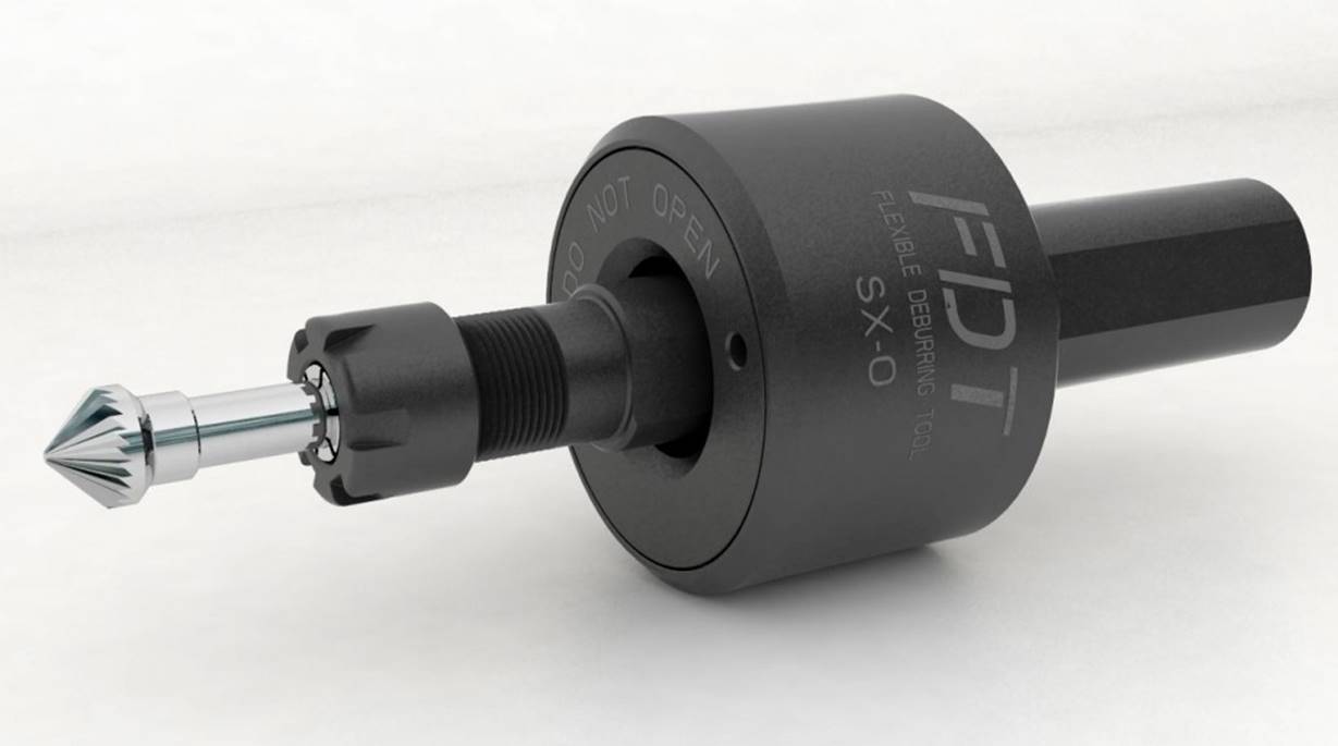
If there are no special circumstances, it is strongly recommended to use our standard length rotary file SK-3M-SC, and the maximum floating amount of this rotary file is 5mm. If a larger floating amount is required, a 100 long rotary file can be selected: SK-3M-SC-100, because the longer the length of the rotary file, the greater the possibility of tool jumping.
型号 | Dc | L2 | D2 | L1 |
SK-3M-SC | 9.5 | 4.7 | 6 | 51 |
SK-3M-SC-100 | 9.5 | 4.7 | 6 | 100 |

According to the processing flow, we first program:
Rotary file can only be milled forward.
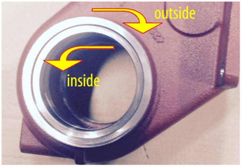
When programming, please follow the processing path in strict accordance with the following requirements:
For the floating deburring chamfering cutter, the machining of the inner corner (the junction of both sides) is slightly more complex. Generally, the cutting head cannot contact the two surfaces perpendicular to the inner corner at the same time, because the imbalance of the force generated by machining the two surfaces at the same time is easy to cause the vibration of the tool. We suggest adding a tool path where the cutting head (rotary file or chamfering cutter) does not contact both vertical sides at the same time. When approaching such an internal angle, the tool shall be properly lifted up to make the top of the taper cutting head contact the workpiece, so that the cutting head can approach such an internal angle more easily (Note: when cutting the top of the head, the machining speed shall be reduced.) When machining to the vertical internal angle of the workpiece, it is necessary to complete the machining of the internal angle through the arc program.
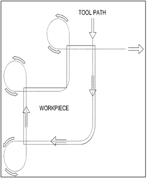
When machining external corners, it is necessary to change the machining direction outside the workpiece (as shown in the figure)
We give the recommended processing parameters. Please follow our initial recommended processing parameters when using it for the first time:
Speed: 3000-8000rpm (5000rpm is recommended at the beginning)
Feed: 2000-5000mm / min (3000mm / min is recommended at the beginning)
Then we will adjust the tool and need to give a 1-3mm pre pressing amount between the rotary file and the workpiece. You can design and program according to the workpiece contour drawing.
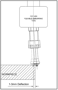
It is recommended to use the middle and rear part of the edge of the rotary file to participate in cutting. The chip removal groove at the front edge of the rotary file is too small, which may not produce cutting, but extrusion, resulting in secondary burr.
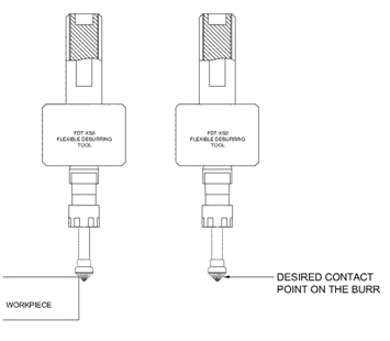
Well, you can already use the floating deburring tool handle. Let's take a look at the processing results. Usually, the first use can meet the requirements of most customers, but some conditions will occur because the tool handle is not pre adjusted according to the customer's processing materials and other factors. Let's solve them together (actually very simple)
The most common problem we encounter is: uneven chamfer and potholes.
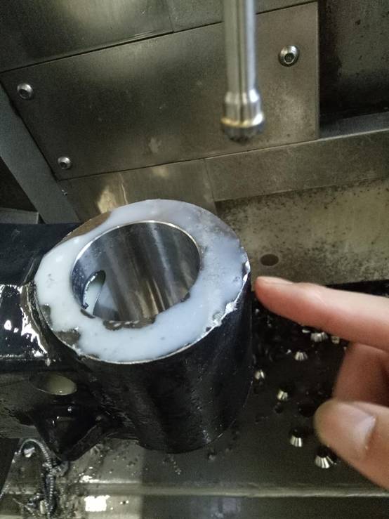
This situation is caused by tool jumping, which will damage the machine tool spindle for a long time.
1. We prefer to increase the elastic pressure to restrain the tool runout, which can be adjusted by the screw at the back of the tool handle. The problem of tool jumping can usually be solved by increasing the elastic pressure. 2. Increase the lateral press in. 3. Increase the speed.
The following are other problems and solutions that may be encountered in the process of using the floating deburring tool handle, and it is usually easy to adjust, so we don't explain too much. Please check it yourself.
Excessive chamfer:
1. Increase feed
2. Reduce the lateral pressing amount (too small lateral pressing amount will cause tool runout and damage the workpiece, tool and machine tool)
Inconsistent chamfer:
1. The feed speed is not constant due to the change of direction - reduce the feed (applicable to the inconsistent chamfer when changing the machining direction)
2. Feed too low - increase the feed speed (applicable to inconsistent chamfers caused by non changing the machining direction)
3. The tool position (pressing amount) is not adjusted well - the lateral pressing amount is 1-3mm
Too small chamfer:
1. Reduce feed
2. Increase lateral pressure
3. Reduce the spindle speed
 简体中文
简体中文 
